Views: 0 Author: J-VALVES Publish Time: 2026-10-05 Origin: Site


A plug valve opens, closes and isolates flow through the close fit between the plug and the seating surfaces of the body. The design is simple, the flow path is unobstructed and operation is fast, which is why plug valves are widely used in oil and gas, chemical processing, water treatment and pharmaceutical piping.
Because the design is simple, performance rests almost entirely on the quality of fit between two surfaces: the internal seating surface of the body and the sealing surface of the plug. There is no elastomeric element acting as the primary sealing barrier for automatic compensation — sealing relies on direct contact between the mating surfaces. The practical consequence is that every single valve has subtly different fit conditions. Casting tolerances, machining allowances, lapping depth, ambient temperature and humidity all turn "one drawing" into "slightly different physical parts".
Automated assembly excels at repeating an identical motion. Plug valve assembly instead requires a fit judgement made for this specific unit. How far should the plug be inserted before it is seated? What rotational resistance indicates a correct fit? What surface sheen after lapping indicates proper contact? These judgements draw on accumulated tactile and visual experience — a genuine human advantage zone.
To be precise: this is not a broad claim that "hand work beats machines". The accurate statement is that the final fitting operation of a plug valve is still predominantly manual, while automation handles rough machining, cleaning, handling and data recording. This follows from the nature of the process, not from a lack of technology.
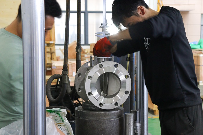
The sequence below follows a typical manual assembly line. Individual manufacturers divide the steps differently, but the underlying logic is consistent.
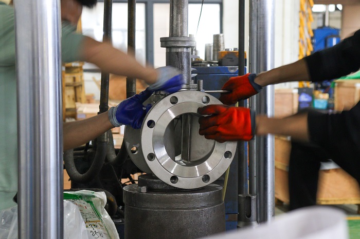
Before the body reaches the assembly station it undergoes ultrasonic or high-pressure washing, after which each bore is visually inspected. Points to check include flow path clearance, seating surface condition, thread or flange integrity, and legibility of the casting marks and material designation. This step sets the baseline quality for everything that follows.
This is the most skill-intensive operation in plug valve assembly. The goal of lapping is not to produce a polished surface, but to achieve uniform contact across the entire mating area. The standard method is to apply a marking compound (red lead or a purpose-made bluing paste), mate the plug to the body and observe the distribution of the marking.
Uniform marking: contact is well distributed and the fit is good.
Marking concentrated in the middle or at the edges: indicates a taper deviation or geometric distortion requiring further lapping or rework.
Broken, intermittent spots: indicates high points or embedded foreign matter; clean and re-lap.
This step depends entirely on the operator's visual judgement and feel, and is where the irreplaceability of manual assembly is most evident.
Depending on construction, plug valves fall into unlined metal-seated, lined (PTFE, PFA and similar) and lubricated types. Alignment requirements differ accordingly:
Metal-seated: the priority is eliminating misalignment, which would cause one-sided loading and stiff operation.
Lined: the priority is protecting the liner from scoring; a guide fixture must be used and direct hammering is not permitted.
Lubricated: the priority is a clear grease passage and accurate control of grease volume.
The most common mistake at this stage is excessive force. Fitting a plug inherently involves some interference. If the operator resorts to striking the plug into position, the seating surface is typically dented. The valve may pass testing immediately after assembly and begin to weep shortly after commissioning.
Torque is the most frequently overlooked — and most easily recorded — variable in manual assembly. Too little torque leaves the seating surfaces under-compressed, and internal leakage can appear even at low pressure. Too much torque accelerates seat wear, increases operating torque and can distort the body or plug.
Deviation | Immediate effect | Impact on the end user |
Torque too low | Insufficient compression, incomplete contact | Internal leakage at low pressure or no load; higher risk of media seepage |
Torque too high | Localised seat crushing and material deformation | Higher operating torque, stiff operation, shortened service life |
Uneven torque (one-sided loading) | Plug deflection with uneven clearance distribution | The classic "leaks on one side, binds on the other" failure |
The correct practice is to use a torque-indicating wrench, apply force in stages in a diagonal sequence, and record the actual torque value for every unit. These records serve not only as quality evidence but as the single most valuable data set during later troubleshooting.
After assembly, the operator performs several full-stroke open-close cycles by hand, judging for binding, unusual noise or distinct torque spikes. An experienced assembler can detect early warning signs through feel that instrumentation may not capture — localised high points, retained debris or inadequate lubrication, for example.
Pressure testing closes the quality loop. It normally comprises a shell strength test and a seat sealing test. Records must capture pressure value, hold time, pressure drop and ambient temperature. For more demanding services, a low-pressure air seal test (for example at 0.6 MPa) is added to catch micro-leaks that a hydrostatic test would miss.
An often-overlooked point
A valve that passes hydrostatic testing and still shows bubbles under air testing is a familiar situation with plug valves. Gas molecules are far smaller than liquid molecules and penetrate micro-channels far more readily. If your service involves gas or volatile media, an air seal test should be an acceptance requirement rather than an optional extra.
Conforming products receive a nameplate (size, material, pressure class, batch number and serial number), corrosion protection on the seating surfaces and end caps for port protection. Assembly torque, pressure test data, the assembler's identity and the date are filed against that specific unit. This step is what turns a "conforming product" into a "traceable product".
A common procurement misjudgement is treating certificates and glossy brochures as proof of quality. A certificate demonstrates that a system exists; assembly quality demonstrates how an individual valve was actually built. The two are not interchangeable.
What genuinely reduces risk is requiring process records from the supplier. The checklist below can be used directly in supplier audits:
Check item | Acceptance basis | Record to retain |
Bore cleanliness | No sand, burrs or chips; clear flow path | Signed in-process inspection |
Seat contact quality | Continuous, evenly distributed marking pattern | Contact check photo or inspection record |
Plug alignment | Guide fixture used; no hammer marks | Fixture usage and process compliance record |
Assembly torque | Within design range; staged diagonal application | Torque wrench readings (per unit) |
Operating torque | Full stroke free of binding or torque spikes | Operating torque measurement record |
Shell strength test | No leakage, no visible deformation | Pressure value and hold time record |
Seat sealing test | Pressure drop within allowance; air test passed for gas service | Test curve or data sheet |
Marking and protection | Legible, complete nameplate; end caps fitted | Serial number and batch archive |
Symptom | Likely cause | Suggested action |
Internal leakage at low pressure | Insufficient assembly torque; inadequate seat contact | Review torque records; re-check contact with marking compound |
Stiff operation, high torque | Over-tightened; damaged seating surface; insufficient lubrication | Check for crushing; restore lubrication; re-verify assembly torque |
One-sided leakage | Plug misaligned, uneven clearance | Inspect alignment on teardown; confirm guide fixture was used |
Passes hydrostatic, micro-leaks on gas | Micro-channel permeation; test medium difference | Add air seal test; improve lapping precision on the seating surface |
Leakage after a period in service | Seat wear; liner ageing; media corrosion | Reassess material and liner compatibility against service conditions |
Precision manufacturing in plug valves ultimately comes down to two dimensions. The first is geometric precision: seating surface contact, plug alignment and uniformity of fit clearance. The second is documentary precision: torque records, pressure test curves and per-unit traceability.
Manual assembly has endured in this product category not because automation is impossible, but because the final fitting judgement benefits from human perception and experience. Once that is understood, procurement and acceptance criteria shift from "check the appearance, check the certificate" to "review the process records, review the data loop" — which is the most effective way to control risk.